
An instrument or apparatus for measuring minute quantities of electricity, or the operations of galvanism.
GALVANOMETER, an instrument used for indicating or measuring currents of electricity, wherein advantage is taken of the force exerted by such currents on movable magnets in their neighbourhood. When a galvanometer is used for indicating merely, without measuring, it is sometimes called a galvanoscope. If we consider only such instruments as have come into actual use, this definition is strict enough for practical purposes. If we were to consider all the instruments that have been or might be made, some would come under the definition whose resemblance to the modern galvanometer would not at first sight be apparent. Such, for instance, is the electromagnetic balance of Becquerel, which consists of two bar magnets hung from the scale pans of a delicate balance each in the axis of a cylindrical bobbin of wire—one being over, the other under its corresponding bobbin (see fig. 1). The north poles of both magnets hang downwards, and the current to be measured is sent round the bobbin, so that each of the magnets is repelled. Weights are put into the left-hand scale until equilibrium in the original position is restored. The weight thus added is proportional to the current strength, so long as the induced magnetism of the magnets can be neglected. This instrument has fallen into disuse.
Tn a complete galvanometer of modern construction the following parts may occur (1) the coil or multiplier, (2)...
the needle or movable magnet or magnets, (3) the astatizing apparatus, (4) the deflecting or adjusting magnet, (5) the graduation or reading apparatus, (6) the damping apparatus, (7) accompanying the galvanometer, as a piece of auxiliary apparatus, we may also have a box of shunts. It would be easy to make a more minute enumeration of parts, but the above will serve our present purpose. On the other hand, it is not always that each of the above organs is represented separately; some may be wanting in certain cases, aud the functions of two or more may be combined.
1. The multiplier or coil consists of a ring-shaped channel of elliptical, rectangular, or circular shape—usually the last, the cross section being in general rectangular. Into this is wound, as closely and regularly as possible, a quantity of silk-covered wire. The material chosen for the wire is usually copper, which should be as soft as possible in order to secure high conductivity. White silk is preferred for the insulating covering, on account of its freedom from iron, though this is for most purposes a needless refinement. Great care should be taken that the wire is dry when it is wound. It is usual, in order to secure and render permanent the insulation, to steep the whole coil in melted paraffin; after this has been done, there is little risk of loss of insulation, provided the layers have been carefully tested during the winding. The idea of the multiplier in sensitive galvanometers is to bring the greatest number of coils of wire within the least possible distances of the magnet. It is evident, therefore, that the insulating covering should be as thin as is consistent with good insulation; this consideration assumes great importance when coils of very fine wire have to be wound. After the wire lias reached a certain fineness the proportion of space occupied by insulating matter is so great that further reduction of the section of the wire simply increases the resistance without enabling us to pack more turns into the same space. In general the section of the wire ought to be chosen with reference to the use which the galvanometer is intended to serve. The following ideal case will enable the reader to comprehend the principle which regulates the choice of multiplier under given circumstances. Suppose the dimensions of the channel, and the whole space which the wire is to fill, to be given, and the whole external resistance also given, then it may be shown that the section of the wire ought to be chosen so that the resistance of the galvanometer shall be equal to the external resistance. The case contemplated here is that where we have a simple external circuit; many cases can be reduced to this at once, and we shall consider below a more complicated case of considerable practical importance. Theoretically the section of the wire ought to vary with the distance of the winding from the axis of the coil. The law is that the diameter of the wire in each layer ought to be proportional to the linear dimension of that layer. This is sometimes roughly carried out in practice by winding the outer layers of thicker wire than the inner. The proper form of the longitudinal section of the coil depends on the use for which the Instrument is destined, and will be more properly discussed when we describe particular instruments. In a certain class of galvanometers called differential, the wire on the coil is wound double, so that two currents can be sent through side by side in the same or in opposite directions.
2. The needle consists of a piece of magnetized steel, which should be as hard as possible. Watch-spriug steel is sometimes used, and file steel is recommended by some authorities. The hardness is important for two reasons,— in the first place, to ensure that the permanent magnetism of the needle shall not alter. This is of small importance where permanent deflections are to be observed, provided we can be sure that the direction of the magnetic axis does not alter. In the second place the induced magnetism is less in hard than in soft steel, though not so much less as some writers would lead us to suppose. The best way of avoiding iuduced magnetism would be to make the needle spherical in form; the advantage thus gained, however, would in most cases be counterbalanced by other defects.
The form of the needle has been much varied by different constructors. In the earlier instruments they were made very long, and were suspended like compass needles by means of a jewelled cup playing on a steel point. We have heard on good authority that for some purposes, such as mounting tangent galvanometer needles, this method of suspension, if carefully carried out, really answers very well. By far the most usual mode of suspension, however, is by means of a raw silk fibre, or by a bundle of such fibres. Weber introduced the use of heavy magnets whose moment of inertia and time of oscillation were great. For many purposes such needles have great advantages—where, for instance, the time of oscillation, the logarithmic decrement, or the extent of swing of the needle has to be observed. Where, on the contrary, the galvanometer is to be used merely as an indicator, particularly in detecting transient currents, a light needle of small moment of inertia should be used. Continental constructors, no doubt unduly influenced by a reverence for Weber’s methods, have failed to realize this; and we have seen few, if indeed any, instruments by them really well suited for measuring resistances with the Wheatstone’s bridge. This principle has been carried farthest in the galvanometers of Sir William Thomson, in some of which the needle with all its appurtenances weighs little over a grain.
In some galvanometers (e.g., certain telegraphic reading instruments) the needle is movable about a horizontal axis, and is weighted so as to be vertical in its undisturbed position. Owing to the friction at the points where the axis is supported, this method of suspension is useless for sensitive instruments.
3. When, as i≡ usual, the galvanometer magnet is movable in a horizontal plane, the force which balances the electromagnetic force of the current in the multiplier is the horizontal component of the earth’s magnetic force. Each of these forces is proportional to the magnetic moment of the galvanometer needle, and consequently the ratio of the forces, on which depends the magnitude of the deflexion of the needle, is independent of the magnetic moment of the needle. We cannot therefore increase the sensitiveness of the galvanometer by simply increasing the magnetic moment of the needle. The action of the earth can, however, be counteracted, and the needle rendered more or less astatic in one or other of two ways.
One way is to fix on the same axis of suspension two parallel magnets, whose magnetic moments are as nearly as possible equal, and which are turned opposite ways. The whole system is suspended so that one of the magnets swings inside the multiplier and the other over it, as in fig. 2. Γn more modern instruments, such as those constructed by Messrs Elliot Brothers, the multiplier consists of two equal coils placed one vertically over the other, each enclosing one of the magnets of the astatic system, as in fig. 3. Another method is to place a magnet, or a system of magnets, in the neighbourhood of the galvanometer, so as to counteract the earth’s force. In general, one magnet will suffice, placed vertically under or over the galvanometer, in the magnetic meridian, its north pole of course pointing north. For convenience this magnet should be mounted on a vertical graduated rod, with a rough and a fine adjustment.
In adjusting the sensitiveness of the galvanometer, it will be useful to recollect that the couple tending to bring the needle back to its position of equilibrium varies directly as the square of the number of oscillations which the needle executes in a given time when no current is passing through the multiplier. As the astatizing magnet is brought nearer and nearer to the galvanometer, the oscillations of the needle will be seen to become slower and slower, till at last the equilibrium becomes unstable, and the needle turns round through 180°; after which, on causing the magnet to approach still farther, the rapidity of oscillation increases. If the damping be very strong, and the mirror very light, an intermediate stage called the aperiodic state is passed through.
4. The normal position of the magnetic axis of the needle, when no current is passing, is parallel to the windings of the multiplier. It is particularly necessary that it should be in this position when the galvanometer is being used as a measuring instrument, and it is advisable in any case, since this is the position in which for a given current the electromagnetic action on the needle is greatest. The final adjustment might of course be made by moving the multiplier, but it is far more convenient to move the needle, a magnet being used for the purpose. Sometimes the astatizing magnet is used, but it is better to have a much weaker magnet for the fine adjustment, suspended like the astatizer on a vertical axis, having a vertical motion and a motion of rotation. It is better still to use a magnet placed with its axis in the axis of the multiplier, so that it can be slid backwards and forwards at pleasure. We have seen two such magnets placed side by side, with their north and south and their south and north poles together; this gives a differential adjustment which is very convenient. The main advantage of placing magnets in this way is that we can alter the direction of the lines of force with a minimum effect on the strength of the magnetic field.
5. The graduation or reading apparatus in the older instruments consisted of a pointer or index fixed to the magnet (very often it was the magnet itself), playing over a circular graduation centred as nearly as possible in the axis of rotation of the needle. The mirror method of reading which prevails in most modern instruments was originally suggested by Poggendorff, and carried out in practice by Gauss and Weber. A mirror is rigidly attached to the magnet, so that the reflecting face passes as nearly as possible through the vertical axis of rotation of the needle. The glass of the mirror should be very thin, otherwise a greater or less correction for its thickness will be necessary. In the subjective method of reading, a scale is fixed before the mirror, which is usually plane (it must be well made to be of any use), and the image of the scale is observed by means of a telescope fixed over or under the centre of the scale. The scale divisions are seen to pass the wires of the telescope, and if a circular scale be used, whose centre is in the axis of suspension of the mirror, the difference between the numbers on the cross wires in any two positions of the magnet is a measure of twice the deflection of the magnet. A correction is necessary when a straight scale is used. The reader who has occasion to use the method will find practical instructions, with tables of corrections, in Wiedemann’s Galvanismus, Bd. ii. sec. 181 sqq.∙ 1 Maxwell’s Electricity and Magnetism, vol. ii. sec. 450 sqq. In the objective method, which is more usually practised in this country, the mirror is concave, and reflects the image of a fixed illuminated slit (often furnished with a vertical wire where greater accuracy is desired) upon a graduated scale. The readings are proportional to double the deflexion of the needle, or to the tangent of the double deflexion, according as the scale is circular or straight.
6. By damping is meant the decrease of the extent of the oscillations of the galvanometer needle arising from the dissipation of energy through the resistance of the air, the action of currents induced in neighbouring metallic circuits, the viscosity of the suspension fibre, and so on. There is always more or less damping owing to the first two causes, and possibly the third; but in many cases, where it is desirable that the oscillations should subside very quickly, the damping is purposely increased. In the older instruments the damping arrangement consisted of masses of copper surrounding the magnet. This is carried to the extreme in Wiedemann’s tangent galvanometer, where the needle is ring-shaped, and swings in a ring-shaped cavity not much larger than itself, in the heart of a mass of copper. In the dead-beat galvanometers of Sir William Thomson the magnet with its attached mirror is enclosed in a flat cell, in which it can just move freely to the required extent. The damping, due to the pumping of the air backwards and forwards round the edges of the mirror, is so great that the needle swings off to its position of equilibrium, and remains there without oscillating at all. The same result is attained in Varley’s construction by immersing the needle in a cell filled with liquid.
7. The box of shunts is simply a set of resistances; generally there are three,—⅜th, - δ ⅛-th, and ⅛th of the resistance of the multiplier. When it is required to reduce the sensibility of the galvanometer, the terminals of one of these, say the ⅛th, are connected with the terminals of the multiplier; we thus have a multiple arc in place of the galvanometer, and the current is divided between its branches in the ratio of their conductivities, so that one-hundredth of the whole current flows through the galvanometer. By means of such a box as we have described, we can therefore send through the galvanometer the whole of any current, or the tenth, hundredth, or thousandth part. It must not be forgotten that the introduction of the shunt diminishes the whole resistance of the galvanometer circuit. In most'cases, however, this is of little moment; where necessary, the alteration may be either compensated or allowed for.
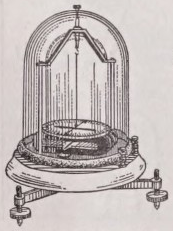
Sensitive Galvanometers.— In galvanometers of this class everything is disposed so as to bring the greatest possible number of turns of wire into the neighbourhood of the needle. The needle is therefore made as small and compact as possible, and the windings embrace it as closely as possible, the opening in the centre of the coil being reduced to a minimum. The astatic multiplier (fig. 4) is an instrument of this kind which was formerly much used. The coil is of flat, rectangular shape, with a narrow central opening just large enough to allow one of the magnets of the astatic system to swing freely. The other magnet swings over a graduated circle placed on the top of the coil, and serves also as an index. Sometimes a mirror and scale are substituted for the index and graduated circle. The sole on which the coil stands is movable on a fixed piece which can be levelled by means of three screws. A graduation is often furnished to measure the angle of rotation of the coil about a vertical axis; this is useful when the galvanometer has to be graduated or corrected for the torsion of the fibre.
In the galvanometers of Sir William Thomson, which are the most sensitive hitherto constructed, the central opening of the coil is circular, being just large enough to allow free play to a small concave mirror a centimetre or so in diameter. Usually the coil is wound in two halves, which can be screwed together with a septum between them, in which is placed the arrangement for suspending the mirror and magnets. In dead-beat instruments the coil is often wound in a single piece, and the mirror is arranged in a cell, glazed back and front, and fitted into a tube which slides into the core of the coil.
Fig. 5 represents a very convenient form of Thomson’s galvanometer, the only specimen of its kind we have seen. The peculiarity of its construction consists in the connexion between the scale and the galvanometer, which saves much trouble in adjusting the instrument. It was constructed by Elliot Brothers for the British Association Committee on Electrical Standards. Such a galvanometer as this, provided with a high and low resistance coil, would meet all the wants of most laboratories.
In another form called the marine galvanometer, the mirror is strung on a fibre stretched between two fixed points. In order to keep the needle from being influenced by the rolling of the ship, its centre of gravity is carefully adjusted so as to be in the axis of suspension. The mirror is enclosed in a narrow cell which just allows it room to deflect to the required extent, and damps the oscillation so effectually that the instrument is “dead beat.” In order to destroy the directive action of the earth, the inconvenience of which in a galvanometer for use on board ship is obvious, the case of this galvanometer is made of thick soft iron, which completely encloses the whole, leaving only a small window for the ingress and egress of the ray of light by means of which the motions of the mirror are read; a flat horse-shoe magnet placed on the top of the case still farther overpowers the earth’s force aud directs the mirror.
All these galvanometers may, of course, be wound double and used differentially. When this is the case, a small auxiliary compensating coil is often used to correct the inequality of the magnetic fields due to the two sets of windings. This auxiliary coil is usually mounted on a spindle in the axis of the main coil, and can be moved backwards and forwards till a current passing through it and one set of windings iu one direction, and through the other set of windings in the other direction, does not sensibly deflect the mirror.
The astatic arrangement described above (p. 51, fig. 4) is often adopted. A galvanometer of this construction by Elliot Brothers is shown iu fig. 6. It may be questioned, however, whether for ordinary purposes the additional sensibility thus gained compensates for the increased complexity and cost of the instrument.
Standard Galvanometers.— When galvanometers are intended for measuring currents, there must be some law connecting the indications of the needle with the strength of the current in the multiplier. It is therefore of great importance that slight variations in the position of the magnet should not introduce Γarge or irregular (incalculable) variations into the indications of the instrument. Accordingly in standard instruments the windings are much farther removed from the magnet than in sensitive galvanometers, and in the best forms the multiplier is so disposed that it produces a uniform field of magnetic force around the needle.
The earliest forms of standard galvanometer were the tangent and sine compasses invented by Pouillet. The first of these consists simply of a single vertical coil of wire, with a magnet suspended at its centre, whose deflexion may be read in any of the various ways already described. If the length of the magnet be very small, the magnetic field in its neighbourhood may be regarded as uniform, and the electromagnetic couple will be proportional to cost?, θ being the deflexion from the plane of the windings. If the windings be arranged so as to be in the magnetic meridian, the couple due to the earth’s...