
A mill operated by the power of the wind, usually by the action of the wind upon oblique vanes or sails which radiate from a horizontal shaft.
WINDMILL. The date when windmills were first erected is unknown; but they were certainly used in Europe in the 12th century. Of late they have generally been replaced by steam engines in Great Britain; but they are still extensively employed in Holland in draining the polders and grinding trass. In America they are largely used; Wolff states that in some cities in the United States over 5000 windmills are manufactured annually. In spite of the competition of more powerful and tractable motors, windmills may often be used with success and economy, especially in new countries where fuel is scarce, and for work which can be done intermittently. The Indian Government recently made inquiries with a view to using windmills for irrigation, and a good deal of information will be found in a report by Colonel Brownlow in the Professional Papers on Indian Engineering, vol. viii. A windmill is not a very powerful motor, and in its employment its power is variable and intermittent. In good situations it will generally work for about eight hours out of the twenty-four on an average. Small windmills are useful on farms for working machines and pumping, in brickfields for pumping, and on ships for clearing out bilge water. They are employed for drainage purposes in Holland and Norfolk, and for mining purposes in some new countries. In America they are used to pump water at railway stations. Sir W. Thomson has proposed to utilize them in charging electric accumulators. As an auxiliary to a steam engine they are sometimes useful; thus at Faversham a 15-horsepower windmill raised in ten months 21,000,000 gallons of water from a depth of 109 feet, saving 100 tons of coal....
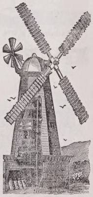
European Windmills.— In all the older windmills a shaft, called the wind shaft, carried four to six arms or whips on which long rectangular narrow sails were spread. The wind shaft was placed at an inclination of 10° or 15° with the horizontal, to enable the sails to clear the lower part of the mill. The whip carrying the sail was often 30 to 40 feet in length, so that the tips of the sails described a circle 60 to 80 feet in diameter. The sails were rectangular, 5 to 6 feet wide, and occupying five-sixths of the length of the whip. A triangular leading sail· was sometimes added. Sometimes the sails consisted of a sail-cloth spread on a framework; at other times narrow boards were used. The oldest mill was no doubt the post mill, the whole structure being carried on a post; to bring the sails to face the wind, the structure was turned round by a long lever. The post mill was succeeded by the tower, smock, or frock mill, in which the mill itself consisted of a stationary tower, and the wind shaft and sails were carried in a revolving cap rotating on the top of the tower. Meikle introduced in 1750 an auxiliary windmill or fan, placed at right angles to the principal sails, for automatically turning the mill face to the wind. If the wind shifts, the small fan begins to revolve and, acting through gearing, rotates the cap of the mill. Mills are exposed to great danger if the sails are not reefed or furled in high winds, and the reefing serves also to prevent the speed of the mill becoming excessive. In 1807 Sir W. Cubitt introduced automatic reefing arrangements. The sails were made of thin boards held up to the wind by a weight. As the strength of the wind increased, the boards were pressed back and exposed less surface.
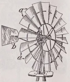
American Windmills. —American windmills generally have the sails arranged in an annulus or disk. The sails consist of narrow boards or slats arranged radially, each board inclined at a constant angle of weather (see below); and the impulse of the wind on these inclined surfaces drives the mill. An American mill presents a larger surface for a given length of sail, and consequently the construction is lighter. To turn the mill face to the wind, a simple large rudder or fish-tail is used, projecting backwards in a plane at right angles to the plane of rotation of the sails. There are a great variety of mills in America, but those most commonly used are of two types. (1) In those which have side-vane governor wheels the action equivalent to reefing the sails is effected by turning the whole wheel formed by the sails oblique to the wind, so as to diminish the wind’s action. A side vane projects in the plane of rotation of the wheel, and the pressure of the wind on this tends to turn the wheel edgeways to the wind. This turning force is counterbalanced by a weight. Hence for moderate winds the wheel is held up face to the wind; for stronger winds it is turned obliquely. (2) In centrifugal governor mills the slats forming the wheel are connected together in sets of six or eight, each set being fixed on a bar at about the middle of its length. By rotating this bar, the boards or slats are brought end on to the wind, the action being analogous to shutting an umbrella. The boards are held up to the wind by a weight, and are also connected to a centrifugal governor. If the speed of the governor increases, the balls fly out and lift the weight; at the same time the sails are partially furled.
Warner’s Annular Sail WindmiU.— Messrs Warner of Cripplegate (London) make a windmill somewhat similar to American mills. The shutters or vanes consist of a frame covered with canvas, and these are pivoted between two angle-iron rings so as to form an annular sail. The vanes are connected with spiral springs, which keep them up to the best angle of weather for light winds. If the strength of the wind increases, the vanes give to the wind, forcing back the springs, and thus the area on which the wind acts diminishes. In addition, there are a striking lever and tackle for setting the vanes edgeways to the wind when the mill is stopped or a storm is expected. The wheel is kept face to the wind by a rudder in small mills; in large mills a subsidiary fan and gear are used. Fig. 1 shows a large mill of this kind, erected in a similar manner to a tower mill. The tower is a framework of iron, and carries a revolving cap, on which the wind shaft is fixed. Behind is the subsidiary fan with its gearing, acting on a toothed wheel fixed to the cap.
Relation between the Velocity of the Wind and its Pressure on Surfaces.— When a flat thin plate is exposed normally to the wind, the pressure on its front surface is increased and that on its back surface somewhat diminished. The resultant total pressure per square foot in the direction of the wind is given approximately by the equation i ,= ∙005 v i (1)
if V is in miles per hour, or i >=∙0023 √≈... (la)
if V is in feet per second. Thus, winds at velocities of 5, 10, and 20 miles per hour would give a pressure of ⅛ lb, ⅛ lb, and 2 lb respectively on each square foot of a surface normal to the wind, and these may be considered ordinary working velocities for windmills. In storms the velocity of the wind may reach a much greater value. Pressures of 28 or 30 tt> per square foot have been frequently registered by anemometers, and at exceptionally exposed stations pressures of 50, 80, and even 90 tt> per square foot have been recorded. These pressures, which are useless for working the windmill, must, nevertheless, be reckoned with in deciding on its structural strength.
Pressure on Surfaces Oblique to the Wind.— The variation of pressure with inclination of surface is only known experimentally.
Let R be the direction of the wind, making an angle θ with the i normal to the surface, supposed to be at rest. Then, if p is the pressure per square foot of surface when the wind is normal to the surface, the resultant normal pressure on the oblique surface is 2cosØ . v f . ,,.
n=Pj—cos 2 ^ per ε 3 uare loot (2).
But the windmill sail moves in a direction perpendicular to the wind. Hence, if v is the velocity of the wind and u that of the sail, the relative velocity is √u 2 + v 2 , and the direction of relative motion can be found as follows. Let aa be the plane of rotation of the sail. The inclination θ of the sail to the plane of rotation is called the angle of weather, and is the same as the angle the wind makes with the normal to the sail. Set off ob = v, bc=u, then oc is the relative velocity, and this makes an angle ≠=tan^ 1 with the direction of the wind and an angle ϴ + Φ with the normal to the sail. Hence for the moving sail
2cos(fl + ≠) . λv + < s >∙
Before replacing p by its value in (1) another consideration requires attention. The sail generally moves faster than the wind; it is not a thin-edged plane, but presents a not inconsiderable surface at right angles to its direction of motion, and thus creates resistance. Of the whole pressure of the wind a part only is effective, the rest being used to overcome the resistance of the sail. It will be assumed that the effective pressure driving the sails is only, for V in feet per second, jo = ’ 001 v t lb per square foot, and, therefore, the effective normal pressure on the sails is, for the relative velocity √v 2 + w 2 , n=∙001(v s +u 2 )j ^-θ~⅛~. The component of this in the direction of motion of the sail is n sin ϴ. Consequently the useful work of the sail expressed in foot-pounds per square foot is sin9 ='°° 1 (" , . +,,i )⅛(⅜+⅜)ιt s (>+⅜) ∙ Bydivldta 8 tl,esail into strips and introducing the known values of u, v, and ϴ the work done is easily found.
Best Angle of Weather.— The best angle of weather is that which lnake3 s^T≠)l⅛07≠) a maximura ∙ τhis K ιves the ve σ simple rule 0 = 67⅜°- ⅛φ. Given the velocity of the wind and that of the tips of the sails, the value of φ is easily found for any point of the sail, and thence θ. Thus, for [table]
Aebrse-Poww of Windmills.— For the older kinds of windmills the following rule derived from some experiments by Coulomb may be used. Let n = no. of sails, A area of each sail in square feet, v velocity of wind in feet per second; then the horse-power of the
τι√4 · ·
mill is i θθo θθ θ; this assumes the speed of the tips of the sails to be about 2⅜ to 3 times the wind velocity. For American wheels Wolff gives the horse-power which may be expected for an average of 8 hours per day as follows :— [table]
Further information will be found in Rankine, The Steam Engine and other Prime Movers; weisbach, The Mechanics of Engineering ; and Wolff, The Windmill as a Prime Mover.