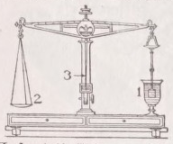
BALANCE. For the measurement of the “mass” of (i.e., of the quantity of matter contained in) a given body we possess only one method, which, being independent of any supposition regarding the nature of the matter to be measured, is of perfectly general applicability. The method—to give it at once in its customary form—consists in this, that after having fixed upon a unit mass, and procured a sufficiently complete set of bodies representing each a known number of mass-units (a “set of weights ”), we determine the ratio of the weight of the body under examination to the weight of the unit piece of the set, and identify this ratio with the ratio of the masses. Machines constructed for this particular modus of weighing are called balances. Evidently the weight of a body as determined by means of a balance—and it is in this sense that the term is always used in everyday life, and also in certain sciences, as, for instance, in chemistry—is independent of the magnitude of the force of gravity; what the merchant (or chemist) calls, say, a “pound” of gold is the same at the bottom as it is at the top of Mont Blanc, although its real weight, i.e., the force with which it tends to fall, is greater in the former than it is in the latter case.
1. Spring Balances. — The general principle of this class of balances is that when an elastic body is acted upon by a weight suspended from it, it undergoes a change of form, which, caeteris paribus, is the greater the greater the weight. The simplest form of the spring balance is a straight spiral of hard steel (or other kind of elastic) wire, suspended by its upper end from a fixed point, and having its lower end bent into a hook, from which, by means of another hook crossing the first, the body to be weighed is suspended,— matters being arranged so that even in the empty instrument the axis of the spiral is a plumb-line. Supposing a body to be suspended at the lower hook, it is clear that the point where the hooks intersect each other will descend from the level it originally occupied, and that it must fall through a certain height h before it can, by itself, remain at rest. This height, provided the spiral was not strained beyond its limit of elasticity {i.e., into a permanent change of form), is proportional to the weight P of the body, and consequently has to the mass Μ the relation Λ = cyM, where c is a constant and g the acceleration of gravity. Hence, supposing in a first case h and Μ to have been h' and M', and in a second case, h!' and M*, we have h': h" :: <7′M′: f'W; and it is only as long as g is the same that we can say K : h! ’ ∙. : M': Μ*. Spring balances are very extensively used for the weighing of the cheaper articles of commerce and other purposes, where a high degree of precision is not required. In this class of instruments, to combine compactness with relatively considerable range, the spring is generally made rather strong; and sometimes the exactitude of the reading is increased by inserting, between the index and that point the displacement of which serves to measure the weight, a system of levers or toothed wheels, constructed so as to magnify into convenient visibility the displacement corresponding to the least difference of weight to be determined. Attempts to convert the spring balance into a precision instrument have scarcely ever been made; the only case in point known to the writer is that of an elegant little instrument constructed by Professor Jolly, of Munich, for the determination of the specific gravity of solids by immersion, which consists of a long steel-wire spiral, suspended in front of a vertical strip of silvered glass bearing a millimetre scale. To read off the position of equilibrium of the index on the scale, the observing eye is placed in such a position that the eye, its image in the glass, and the index are in a line, and the point on the scale noted down with which the index apparently coincides.
2. Chain Balances. — This invention of Wilhelm Weber’s having never, so far as we know, found its way into actual practice, we confine ourselves to an illustration of its principle. Imagine a flexible string to have its two ends attached to the two fixed points C and D (fig. 1), forming the terminal points of a horizontal line CD shorter than the string. Suppose two weights to be suspended, the one at a point A, the other at a point B of the string; the form of the polygon CDBA will depend, caeteris paribus, on the ratio of the two weights. Assuming, for simplicity’s sake, CA to be equal to DB, then, if the weights are equal, say, each = P units, the line AB will be horizontal. But if now, say, the weight at B be replaced by a heavier weight Q, the point A will ascend through a height h, the point B will descend through a lesser height h' in accordance with equation PΛ = QΛ', and the angle between what is now the position of rest of the base line A'B', and the original line AB will depend on the ratio of P: Q. The exact measurement of this angle would be difficult, but it would be easy to devise very exact means for ascertaining whether or not it was horizontal, and, if not, whether it slanted down the one way or the other; and thus the instrument might serve to determine whether P was equal to, or greater or less than, Q; and this obviously is all that is required to convert the contrivance into an exact balance.
3. Lever Balances. — This class of balances, being more extensively used than any other, forms the most important division of our subject. There is a great variety of lever balances; but they are all founded upon the same principles, and it is consequently expedient to begin by summing up these into one general theory.
Theory of the Lever Balance (fig. 2).—In developing the “theory” of a machine, the first step always is and must be that we substitute for the machine as it is a fictitious machine, which, while it closely corresponds in its working to the actual thing, is free from its defects. In this sense what now follows has to be understood. Imagine an inflexible beam suspended from a stand in such a manner that, while it can rotate freely about a certain horizontal axis fixed in its position with respect to both the stand and the beam, and passing through the latter somewhere above its centre of gravity, it cannot perform any other motion. Imagine the beam at each end to be provided with a vertical slit, and each slit to be traversed by a rigid line fixed in the beam in such a situation that both lines are parallel to, and in one and the same plane with, the axis of rotation; and suppose the mass of the beam to be so distributed that the line connecting the centre of gravity S with its projection 0 on the axis of rotation stands perpendicular on that plane. Suppose now two weights, P' and P", to be suspended by means of absolutely flexible strings, the former from a point A on the rigid line in the left, the other from a point B on the rigid line in the right slit, and clearly, whatever may be the effect, it will not depend on the length of the strings. Hence we may replace the two weights by two material points situated in A and B, and weighing P' and P* respectively. But two such points are equivalent, statically, to one point (weighing P' + P") situated somewhere in D within the right line connecting A with B. Suppose the beam to be arrested in its “normal position” (by which we mean that position in which AB stands horizontal and the line SO is a plumb-line), and then to be released, the statical effect will depend on the situation of the point D, and this situation, supposing the ratio l': I" to be given, on the ratio P': P' ’. If P ’ l' = P" I", D lies in the axis of rotation; the beam remains at rest in its normal position, and, if brought out of it, will return to it, being in stable equilibrium. This at once suggests two modes of constructing the instrument and two corresponding methods of weighing.
First Method.— We so construct our instrument that while ΐ is constant, I" can be made to vary and its ratio to ΐ be measured. In order then to determine an unknown weight P', we suspend it at the point pivot A; we then take a standard weight P" and, by shifting it forwards and backwards on AB, find that particular position of the point of suspension B, at which P* exactly counterpoises P'. We I" I" then read off y , and have P' = P*y. But, practically, the body to be weighed cannot be directly suspended from A, but must be placed in a pan suspended from A, and consequently the weight p 0 of the pan and its appurtenances would always have to be deducted from the total weight P', as found by the experiment, to arrive at the weight of the object p ≈ P' - p 0 . Hence, what is actually done in practice is so to shape the right arm that its back coincides with the line AB, and to lay down on it a scale, the degrees of which are equal to one another, and to l' (or some convenient submultiple or multiple of l') in length, and so to adjust p 0 and number the scale, that when the sliding weight P" is suspended at the zero-point, it just counterpoises the pan; so that when now it is shifted successively to the points 1, 2, 3 . . . p, it balances exactly 1, 2, 3 . . . p units of weight placed in the pan. This is the principle of the common steel-yard, which, on account of the rapidity of its working, and as it requires only one standard weight, is very much used in practice for rough weighings, but which, when carefully constructed and adjusted, is susceptible of a very considerable degree of precision. In the case of a precision steel-yard, it is best so to distribute the mass of the beam that the right arm balances the left one + the pan, to divide that arm very exactly into, say, only 10 equal parts, and instead of one sliding weight of P" units to use a set of standards weighing P ,, , τ ⅛ P", τ ⅛ σ P", 10 1 0 σ P", &c. The great difficulty is to ensure to the heavier sliding weights a sufficiently constant position on the beam. To show the extent to which this difficulty can be overcome it may be stated that in an elegant little steel-yard, constructed by Mr Westphal of Celle (for the determination of specific gravities), which we had lately occasion to examine, even the largest rider, which weighs about 10 grammes, was so constant in its indications that, when suspended in any notch, it always produced the same effect to within less than 3 0 1 0 - σ th of its value.
Second Method.— We so construct our instrument that both l' and Γ have constant values, and are nearly or exactly equal to each other, and provide it with pans, whose weights p 0 ' and pf are so adjusted against each other that p' l' = pfl', and, consequently, the empty instrument is at rest in its normal position. We next procure a sufficiently complete set of weights, i.e., a set which, by properly combining the several pieces with one another, enables us to build up any integral multiple of the smallest difference of weight δ we care to determine, a set, for instance, which virtually contains any term of the series 0Ό01, 0Ό02, 0.003 100'000 grammes. In order now to determine an unknown weight p', we place it, say, in the left pan, and then, by a series of trials, find that combination of standards p>' which, when placed in the right pan, establishes equilibrium to within ± δ. Evidently— ∕-fci≡ d).
In the case of purely relative weighings, there is nothing to
Γ ∕ I" ∖ hinder us from adopting y units (e.g., y grammes! as our unit of mass, and simply to identify the relative value of p' with the number p'. But even if we want to know the absolute value of p in true grammes, we need not know the numerical value of —. AU we have to do is, after
Γ ’ having determined the value of p' in terms of y, to reverse the positions of object and standards, and, in a similar manner, to ascertain the value p 1 " which now counterpoises the unknown weight p' lying in the right pan. Obviously p' ^P" γ= Pi" (pΥ≈p"pι'∙> and P' = *Jp v p"> for which expression, if the two arms are very nearly of equal length, we may safely substitute p' = ⅛(p" +p 1 "). Or, instead of at once finding the counterpoise for p' in standards, we may first counterpoise it by means of shot or other material placed in the opposite pan, and then find out the number of grammes p" which has to be substituted for p' to again establish absolute equilibrium. Evidently p' = p". This (in reference to the ideal machine meant to be realised) is the theory of the common balance as we see it working in every grocer’s shop, and also that of the modern precision balance, which, in fact, is nothing but an equal-armed beam and scales refinedly constructed. In the case of the latter class of balances the inconvenience involved in the use of very small weights may be avoided (and is generally avoided) by dividing the right arm of the beam, or rather the line AB, into 10 equal parts, and determining differences of less than, say, 0Ό1 gramme by means of a sliding weight possessing that value. But evidently, instead of dividing the whole length of the right arm, it is better to divide some portion of it which is so situated that the rider can be shifted from the very zero to the “10,” and so to adjust the rider, that when it is shifted successively from 0 to 1, 2, 3 . . . n it is the same as if 1, 2, 3 . . . n tenths of its weight were placed in the right pan. The rider in this case must, of course, form part and parcel of the beam. It is singular that none of our precision-balance makers have ever thought of this very obvious improvement on the customary system. In the very excellent instrument made by Messrs Becker and Company of New York, this, it is true, is realised partially in a rider weighing 12 milligrammes and a beam divided into 12 equal parts (instead of 10 and 10 respectively); but this does not enable one to shift the rider to where it would indicate from 0 to say -⅛ or 1 ⅛∙ of a milligramme. Whichever of these modes of weighing we may adopt, we must have an arrangement to see whether the balance is in its normal position, and it is desirable also to have some means to enable us, in the course of our trials, to form at least an idea as to the additional weight which would have to be added to the standards on the pan (or to be taken away) in order to establish equilibrium. To define the normal position, all that is required is to provide the beam with a sufficiently long “needle,” the axis of which is parallel to the line OS, and which plays against a circular limb fixed to the stand and constructed so that the upper edge of the limb coincides very nearly with rhe path of the point of the vibrating needle, and to graduate the limb so that, as fig. 2 shows, the zero point indicates the normal position of the beam. In order to see how the graduation must be made to be as convenient as possible a means for translating deviations of the needle into differences of weight, let us assume the balance to be charged with P' grammes from A and with P" + Δ grammes from B, and P' and P" to satisfy the equation P' l' = P"Z ’ '. The two weights P' and P' being equivalent to one point P' + P" in the axis of rotation, the effect is the same as if these two weights did not exist and the beam was only under the influence of two weights, viz., the weight W of the beam acting in S and the weight Δ acting in B. But this comes to the same as if both W and Δ were replaced by one point weighing W + Δ, and situated somewhere at C o between, and on a line with, B and S. Hence, supposing the beam to be first arrested in its normal position and then to be left to itself, the right arm will go down and not be able by itself to remain at rest before it has reached that position in which C o lies vertically below the axis of rotation. Coeteris paribus C o will be the nearer to B, and consequently the angle α, through which the beam (and with it the needle) has to turn to assume what now is its position of stable equilibrium, will be the greater the greater Δ is, and for the same Δ and W the angle of deviation will be the greater the less the distance s of the centre of gravity of the beam S is from the axis of rotation. The former proposition enables one in a given case to form an idea of the amount Δ which has to be taken away from the right pan to establish equilibrium. To find the exact mathematical relation between Δ and the corresponding angle α, let us remember that the position of C o is the same whatever may be the direction of gravity with regard to the beam. Assuming gravity to act parallel to OS, we have (W + Δ) CC 0 = ΔZ", where C stands for the projection of C o on OS. Assuming, secondly, gravity to act parallel to the line OB, we have (W + Δ). C0 = W. OS;
CC 0 ÷ ∕O<
CO Ws v '
Obviously, the right way of graduating the limb is to place the marks so that their radial projections on the tangent to the circle at the zero-point divide that line into parts of equal length. In the Ordinary balance where Z" is a constant, the factor — has a constant value, which can be determined by one experiment with a known Δ—always supposing that in the instrument used the requirements of our theory were exactly fulfilled. In good precision balances they are fulfilled, to such an extent at least, that although the factor named is not absolutely constant, but a function of P, it can be looked upon as a relative constant, so that by determining the deviations produced by a given Δ, say Δ = 1 milligramme, for a series of charges (z.e., values of P"), one is enabled to readily convert deviations of the needle, as read off on the scale, into differences of weight. This method is very generally followed in the exact determinations of weights as required in chemical assaying, in the adjusting of sets of weights, &c. Only, instead of letting the needle come to rest and then reading off its position, what is done is to note down 2, 3, 4 . . . n consecutive excursions of the needle, and from the readings (α 1 , a i , α 3 , a i . . . α β ) to calculate the position a 0 where the needle would come to rest...